|

|
High Energy Site
|
|
Experimental Site
The initial proton beam for PIF is
delivered from the PROSCAN accelerator with
the help of the primary energy degrader, which allows setting the initial
beam energy
from 230 MeV down to 74 MeV.
The beam is subsequently guided to the Experimental
Area where PIF facility is located.
Having energy of the beam degraded directly after accelerator exit causes
also
its intensity reduction on target.
Additional safety reasons put the maximum beam intensity in the PIF area up
to
2 nA for energies above 200 MeV,
5 nA for energies from 100 MeV
to 200 MeV and
10 nA for energies below 100 MeV.
As PROSCAN accelerator serves also two GANTRY stations
and OPTIS2 facility for the cancer treatment, most of PIF exposures are
conducted
during weekends and short night-shifts.
The PIF experimental area is located in
the PROSCAN accelerator Hall as showed in the Figure below.
Figure
1. PIF-PROSCAN Hall with the PIF Experimental Area.
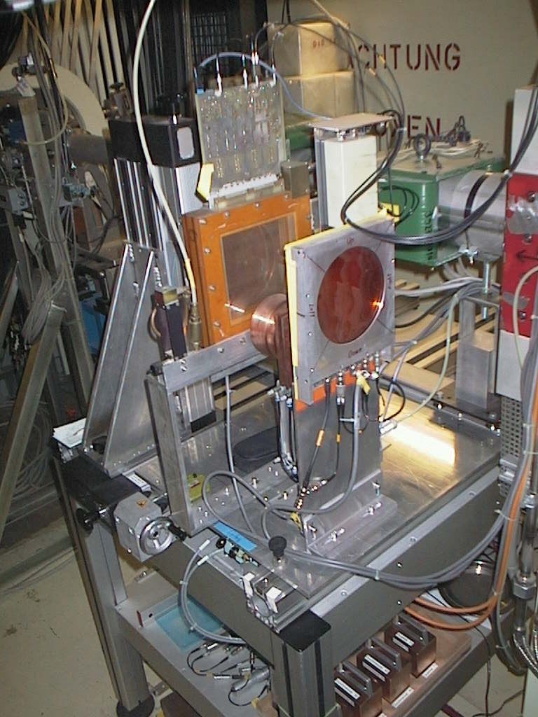
PIF area is equipped with the beam-line
elements and PIF arrangement as showed below (Photo 1).
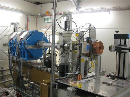
Photo
1. PIF area downstream view with the last quadrupole
magnets, beam monitors and PIF station. One can see the XY-table with beam
collimator.
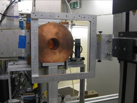
The PIF experimental set-up consists of
the local PIF energy degrader, beam collimating
and monitoring devices (Photo 2).
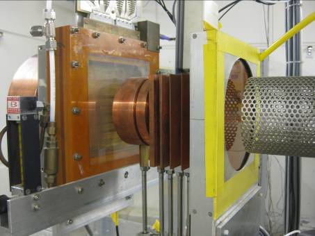
Photo
2. PIF arrangement with the ionization chamber, energy degrader and wire
chamber.
Movable XY table with the sample holder
(see Photo 3) enables easy mounting of the
user's device under test (DUT) on the beam.
Photo
3. PIF arrangement rear view with the XY-table, its movable arm and DUT
sample holder.
The laser mounted downstream from the XY
table allows centering the DUT and control
its position (see Photo 4).
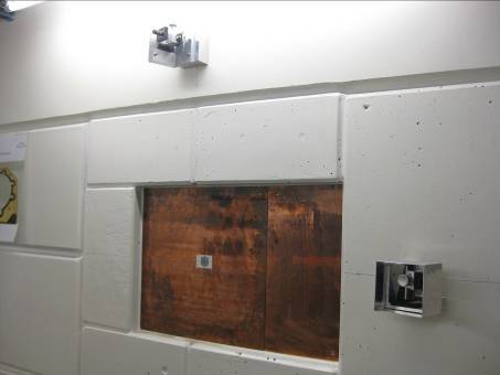
Photo
4. PIF area downstream view with the laser for sample centering and the
beam dump.
Irradiations are usually carried out in
air. The maximum available energy is 230 MeV and
the
maximum current is limited to about 2 nA due to
air activation in the experimental area.
According to the experience and user
requirements, the monitor detectors are selected for each
experiment individually: ionization chambers, Si-detectors, plastic scintillators. In addition, the gamma and neutron dosimetry is routinely performed (see Photo 5 below).
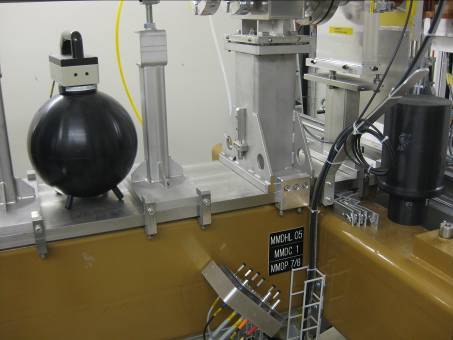
Photo
5. PIF area neutron and gamma dosimeters.
Schematic view of the experimental hall
from the point of view of beam-lines and area locations is shown in Figure
below:
Figure
2. PROSCAN Hall, accelerator, beam-lines and tests areas. PIF site is
marked as ‘EXP.’.
The irradiation is controlled from the
experimental barrack located on top of the PIF area (see Photo below).
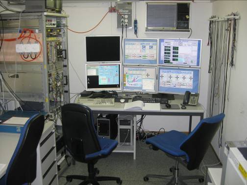
Photo
6. PIF operator table in the barrack.
Beam flux values are monitored through a
set of counters and a PC-based data acquisition system.
The system monitors proton flux and dose rate, calculates the total
deposited dose and
controls the position of the sample as well as beam focus parameters.
It also allows for
setting the beam energy with the help of the PIF local energy
degrader. This makes it
possible to perform fully automated irradiations
with arbitrary proton spectra.
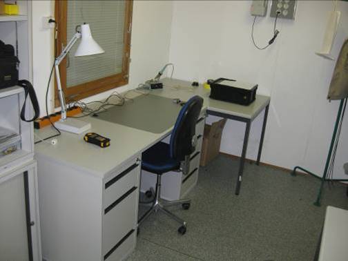
Photo
7. One of the users tables.
The experimenters have for their use and
needs of their data test setup the second part of the PIF barrack as seen
on the Photo above. Standard laboratory and electronic equipments is also
available.
·
Initial
proton energies: 230, 200, 150, 100 and 74 MeV
(can be modified if requested)
·
Energies
available using the PIF degrader:
quasi continuously from 6 MeV up to 230 MeV
·
Energy straggling
for the initial beam energy of 74.3 MeV:
e.g. FWHM=2.4 MeV at 42.0 MeV,
FWHM=5.6 MeV at 13.3 MeV.
·
Maximum beam
intensity at 230 MeV: 2 nA
(at 74.5 MeV ca. 5 nA
effectively)
·
Maximum flux
at 230 MeV for the focused beam:
~ 2*109 protons/sec/cm2
·
Beam
profiles are of Gaussian-form with standard (typical):
FWHM=10 cm
·
Irradiations
take place in air
·
The maximum
diameter of the irradiated area: f 9 cm
·
The accuracy
of the flux/dose determination: 5%
·
Neutron
background: less than 10-4 neutrons/proton/cm2
·
Irradiations,
devices and sample positioning are supervised by the computer
·
Sample
mounting frame 25 x 25 cm2
(SEU and HIF facilities compatible)
is attached to the XY table
·
Data
acquisition system allows automatic runs with user pre-defined
irradiation criteria
|